MB Wooden Railways
A different approach to wooden railways
Welcome to MB Wooden Railways, which is part of a larger site concerned with Miniature Buildings . It discusses aspects of Brio (and compatible) railways and my own, not entirely usual, approach to them. For my other articles on the subject please go to Railways Articles
Brio Bridges
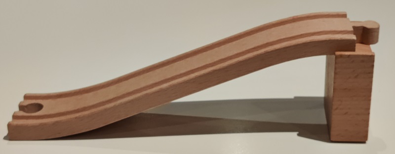
As well as a scratch built layout I also have (for the grandchildren of course) an extensive collection of Brio and other compatible track and associated items. As you would expect these include a variety of bridges. Many of which are based on two pillars at the end of the bridge and two lengths of shaped track which Brio identify (or at least used to identify) as N or N1.
My experience is that these are not without their problems. The frustration is shared by others, it is a theme that keeps repeating in two Facebook groups: Brio Train Builders and Official BRIO Trains Engineers Club. I guess the ascent and descent works well if your children are playing the original games, pushing little trains by hand around a small track. However, most of the time my grandchildren use the battery powered engines. With fresh batteries the slopes are usually OK for an engine by itself. But as they get a bit tired or with wagons behind them they may find the slope a little steep. The other issue is that the track is not really secured to the pillars and as a result the whole edifice is rather fragile and prone to collapse. Especially as toddlers and grandparents lumber around dealing with derailments, stalled trains etc. Which the kids and I all find rather tedious.
A similar issue occurred with the lifting bridge, from Thomas and Friends, discussed in my swing bridge article. My solution there was to add two extra pieces flattening the slope without modifying the bridge itself. There is a whole wiki site devoted to this brand.
The fragility issue is the easier fix. In my view any bridge needs a base of some sort. Before getting into that I'm going to repeat here a passage I wrote in my swing bridge article:
I do like to use little connector pieces when helping the children make a layout. I know the (original) idea is that the joints on wooden track are left a bit flexible to enable everything to join up but my experience with children is that the track is easily knocked and displaced - especially when two or more are careering about trying to participate in the fun! To avoid this I have made lots of simple connector plates to steady the joints.
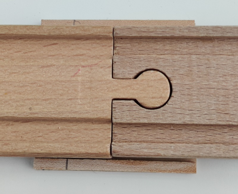
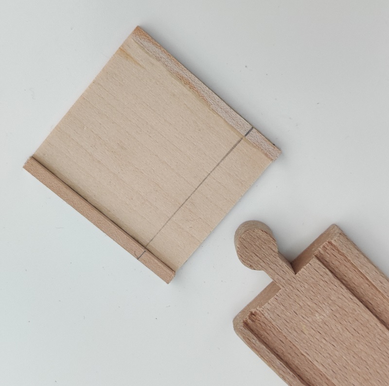
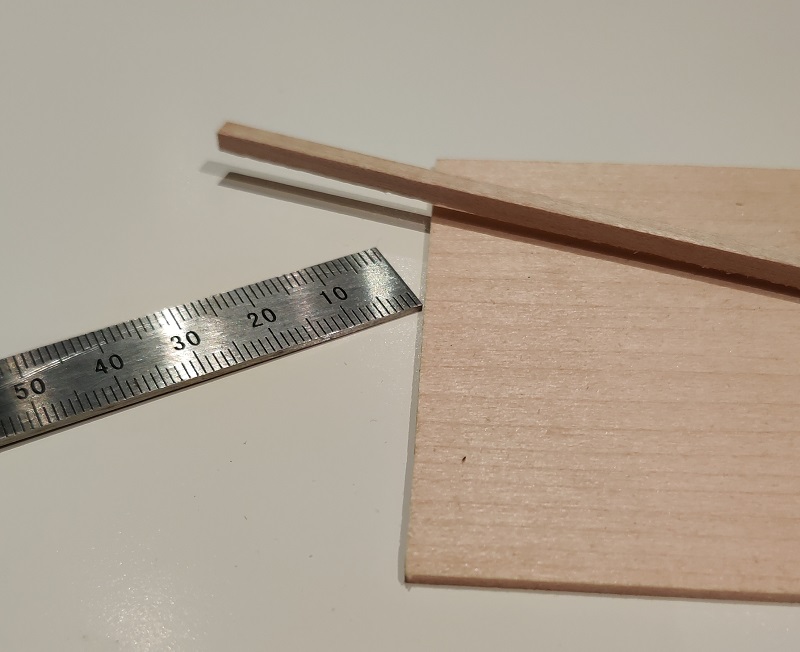
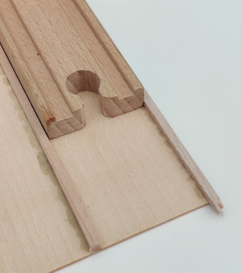
I start with a long strip of the thinnest wood or MDF available - typically 1/32 basswood. The brand I use is Midwest which is certainly available in the UK. The choice of wood and the thickness really doesn't matter. As close in colour to beechwood as possible is obviously nice. 1/16 is OK too as are 1 or 2mm, but the thinner the better really. The strips I have are are 3" x 24" which is a bit of a pain as I can only get one length out of each strip but Midwest is also available in 4" width which would enable two lengths. The strip is needed is (around) 48mm wide. Sorry for mixing up imperial and metric like this. I usually work in metric but the materials I have are defined in imperial. I say 'around' as it depends on the width of the square sections and on the width of the track you are using. Did you realise that the different brands of track have slightly different dimensions? I have so many I'm not sure which is which but Brio is 40mm. I begin by gluing a length of small square section timber (4mm x 4mm) along one edge.
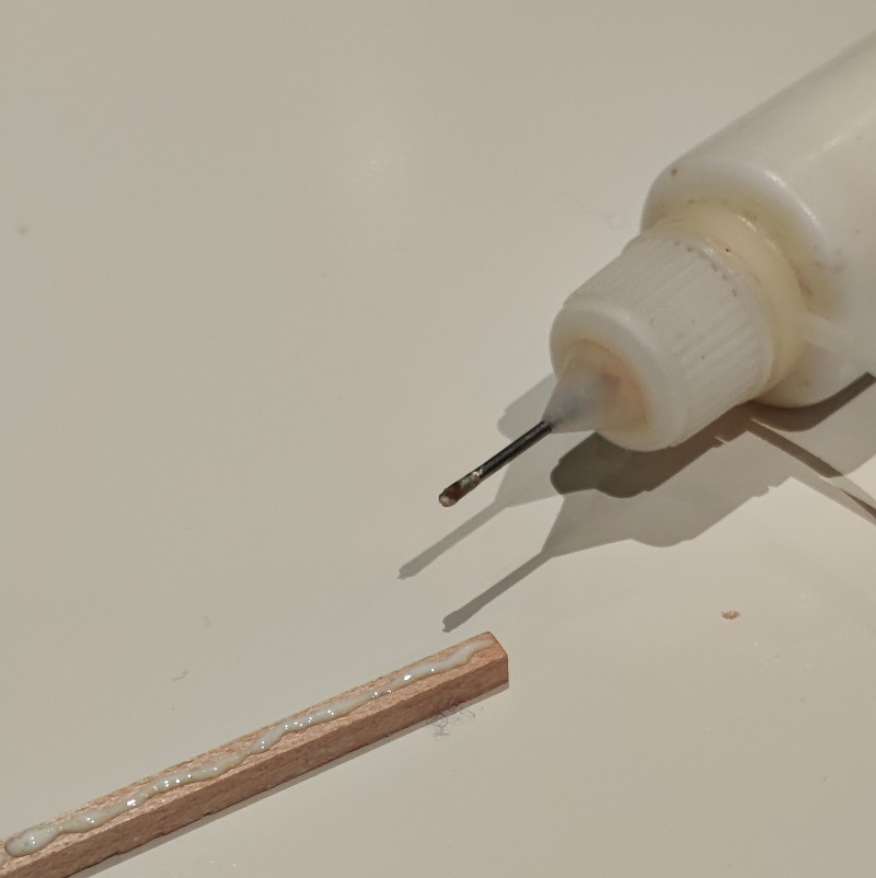
Once this is firm (and any excess glue on the inside has been cleaned up) I lay a piece of track against it and use this as a guide for laying and gluing the second square section. When the glue is fully set I can then cut the strip into short lengths. Typically around 40mm-50mm but the precise length is not critical.
If you are using 4" board this is also a useful way of keeping twin tracks parallel. It just needs one or two more lengths of the square section depending on far apart you want the two tracks.
To get back to the main topic, I use the same materials to make bases for bridges, the ramps leading up to and down from them and the connection to the next track sections, whatever they might be.
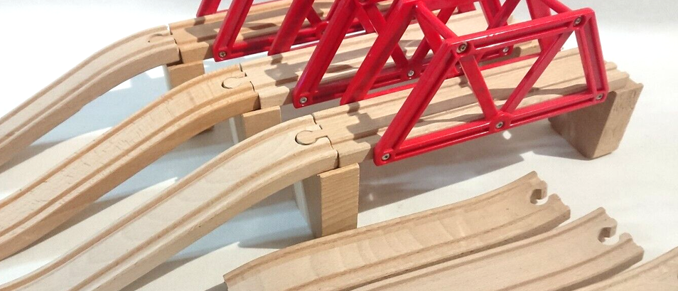
The simplest bridge is this one, which may use a special bridge section as illustrated or may just use the 108mm A track, the 144mm B or the long 216mm D. Or even a curve - as we all have lots of 170mm E pieces. Resting on two simple wooden columns. (The info about track codes comes from the excellent wooden railway.info site,and can also be seen in my tribute page to that site .)
My normal preference is for my modifications to interfere as little as possible with the concept of the child putting together the pieces as they come out of the box but with these simple bridge supports I think a few screws and some glue are worth it. The first stage of this article is so straightforward that the child in your railway can work with you so that they feel it is their adaptation.
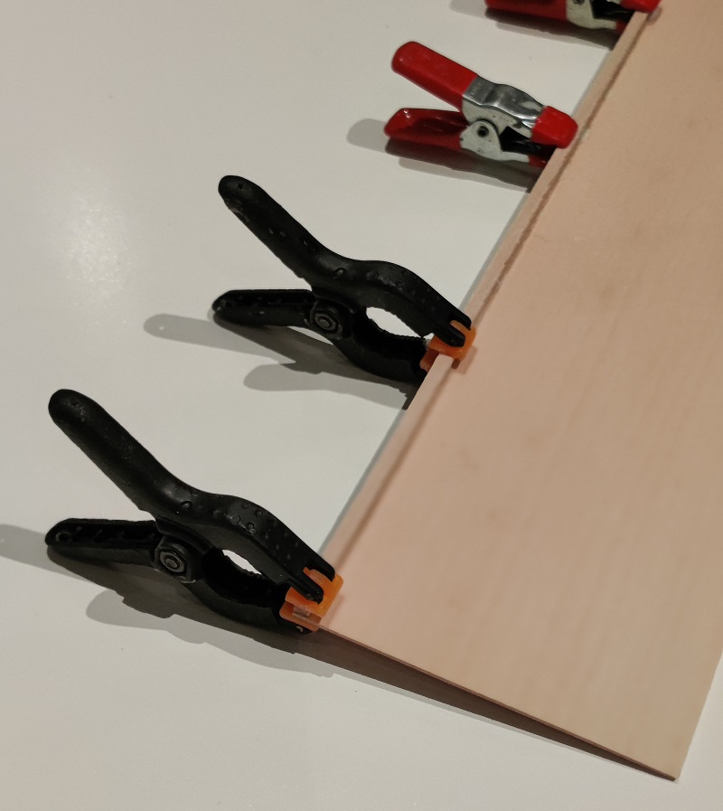
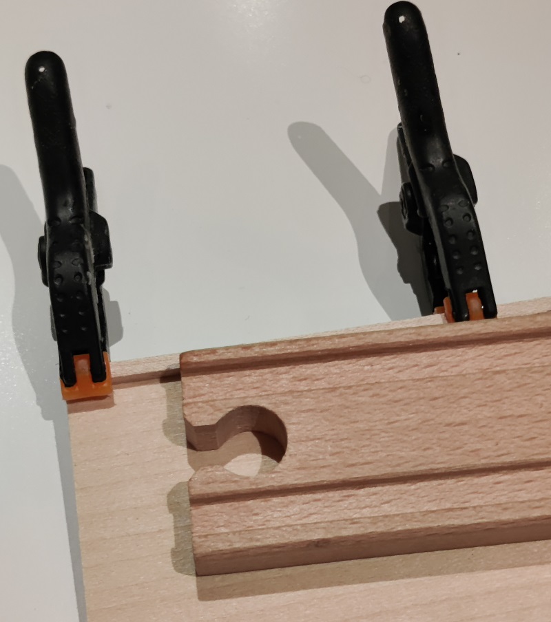
Once you, or the responsible child, have decided which track section to use, the track and two pillars can be glued or screwed (or both) together. This can be done just at the top but a base of thin (1/32" to 2mm) board underneath will make it so much more secure. Before doing this pause to think about the approach ramps - the second step in this article.
If you are going to use the 'out of the box' ramps as they are then you can either continue the fixing process and secure the top of the ramps to the pillars or you can leave them loose and just provide a connection point at the bottom. Either way the base will ideally be the full length of the bridge and its approaches. But it doesn't have to be. If you are not going to make a full length base I do recommend a small strip on the bridge pillars to keep the approach ramps aligned neatly.
But.... all my articles seem to include a 'but' somewhere. As I said at the start, I find the standard N ramps can sometimes be too steep for most battery trains pulling a load. And the transitions from level to climbing and back to level are too sudden. Lots of video clips show sudden jerks at the ttransition points.
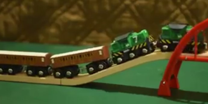
For me the angle at the top and bottom of the slope is just too severe, even though the double headed shunters are able to make the climb. The No. 7 shunter is one of the more powerful engines that are available, as described in my train power article.
Fixing this is rather more radical. The connections at the top and bottom need to be preserved, the middle cut out and a longer length of track inserted in its place at a gentler angle. Which is why I suggested a pause before making the bridge base. This change means it must be longer.
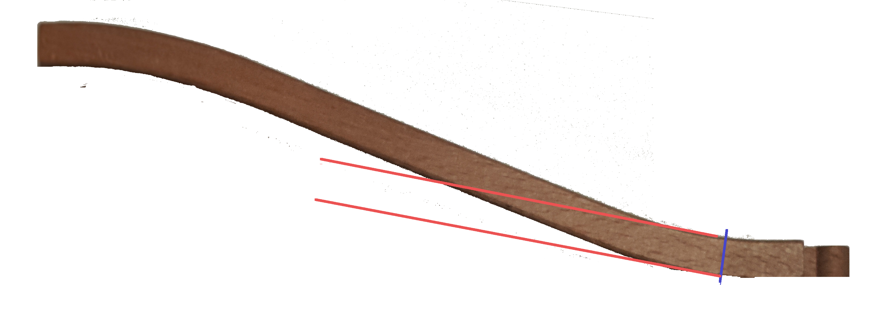
In the example I've illustrated here I made the cuts at 25mm from each end (ignoring the male peg). The longer your inserted section is going to be (i.e. the shallower the desired gradient) the shorter this distance needs to be. I made the cuts at 25mm and then made the middle section to fit - it turned out to be around mm. The new middle section could be a simple 216mm D section but this isn't going to make the gradient much gentler. If you want to use commercial track I would probably use a D length plus an A1 or A length as well. If you are feeling flashy you could include a curve in the approach but be warned - you will need to introduce some sort of camber into the curve. A subject for another day. You could of course make your own track section to exactly the length you want. A subject to be discussed in another article. Without curves this is not a difficult job, the cuts are straight across the track and the glued butt joints can be easily reinforced underneath. Probably with offcuts from the board being used for the base. You might also want to introduce a second, shorter, supporting pillar either made from scratch or a cut down standard one. Remember the top of the new pillar half way up needs to be angled to fit the new slope!
An alternative suggestion from Richard Brotbeck in both Official BRIO Trains Engineers Club and Brio Train Builders is to glue a strip of 150 or 200 grit sandpaper in the track channels of the ramps. Similar suggestions have been made in Brio Train Buiders by Rob Ashman and Gregory Brigman
Mel Barns in BTB Jan24 made the following suggestion. "For ascending ramps, I often use the thomas the train tracks (apologies if this is breaking group rules to go off Brand) because they have a bit more grip to them. With that I can easily pull three . None of my motorized Brio trains seem to cope well with more than one car on hills though otherwise."
You can of course forget about using special ramp sections altogether and simply join two straight sections at an angle though you wil have to trim and fill quie a lot at the join to get it to lie flat and make a smooth transition from flat to the required slope angle. Or you can look at some of the 3D printed offerings, such as this one.
 A piece by 'ratchet hamster' available through Thingiverse
Are these changes worth the effort? They are not a huge amount of work and are mostly cannablalising pieces you already have It did take a while but I'm retired so time is not a big issue and there were a few weeks between one visit from the kleinkinderen and the next. The truth is the standard ramps to the bridge colums were not really useable on a battery powered layout as they were since they were too steep.
Everything I have written above betrays me as old school - sawing, sanding and gluing wooden sections. The new world of 3D printing is rapidly overtaking us though I haven't taken the plunge yet. If you are a modeller that has I would love to host material from you on the process of creating bespoke supports and track lengths.
As always, please
e-mail
Miniature Buildings
if you have something to add. Comments, criticisms,
extra thoughts, pictures, or even complete articles
for inclusion in the Miniature Buildings site
are all welcome. Or if you would like to be added to
my mailing list to hear when a new article is published.
David, March 2024,